
Fluid couplings vs mechanical couplings: which one suits your needs?
2026-11-15 00:53
Author:
Haozong
Article overview
This guide compares fluid couplings and mechanical couplings across performance, cost, compliance, and industry application. It is written for mechanical engineers and procurement professionals operating in Mexico's industrial sector in 2026.
Table of contents
- 1. What are types of couplings? Core definitions
- 2. Mechanical coupling classification: rigid vs flexible
- 3. Fluid couplings: how they work and when to use them
- 4. Head-to-head comparison: data table and key metrics
- 5. Coupling selection guide: step-by-step process
- 6. Failure diagnosis and real-world cases
- 7. Mexico compliance, sourcing, and 2026 market outlook
- 8. Frequently asked questions
What are types of couplings? Core definitions
Types of couplings refers to the classification of mechanical devices that connect two rotating shafts to transmit torque while accommodating axial, radial, or angular misalignment between them. In Mexico's industrial vocabulary, the term "cople" covers everything from a simple rigid sleeve to a hydrodynamic fluid unit driving a 2 MW conveyor motor.
At the broadest level, every coupling belongs to one of two families: mechanical couplings, which rely on physical contact between components, and fluid couplings, which transmit torque through a hydraulic working medium — no metal-to-metal contact required. Understanding where each family fits is the first step in any rational shaft coupling types explained selection process.
Why does the distinction matter? Because each family solves a fundamentally different engineering problem. Mechanical couplings prioritize positional accuracy, compactness, and low cost. Fluid couplings prioritize soft starting, overload protection, and vibration isolation. Choosing the wrong family — not just the wrong model — is one of the leading causes of premature drive-train failure in Mexican manufacturing plants, according to field data compiled by BIOSA México in 2025.
How are couplings categorized in engineering standards?
ANSI/AGMA 9000-D11 and API 610 both segment mechanical coupling types into rigid, flexible-element, and fluid-power categories. Rigid couplings tolerate no misalignment; flexible couplings accommodate small but unavoidable shaft offsets through elastomeric, metallic, or disc elements; fluid couplings decouple driver and driven machines hydrodynamically. Each category carries distinct torque transmission devices design rules, service factors, and maintenance intervals.
What is the role of torque transmission in coupling selection?
Every coupling is ultimately a torque transmission device. The rated torque (TN) must be multiplied by the application service factor (KA, typically 1.25–2.5 for shock loads) to arrive at the required coupling torque rating. Skipping this calculation — and simply matching shaft diameter — is the single most common selection error observed in real installations across the automotive and mining sectors in Sonora and Coahuila.
Mechanical coupling classification: rigid vs flexible
Mechanical couplings divide cleanly into rigid and flexible subtypes, and the distinction shapes every downstream engineering decision. Rigid couplings deliver zero backlash and maximum torsional stiffness; flexible couplings trade some stiffness for misalignment capacity and vibration damping.
Rigid couplings
Rigid couplings — sleeve, flange, and clamp designs — are the simplest power transmission couplings available. They assume perfect shaft alignment and offer no compensation for offset or angularity. In practice, that means they demand laser-aligned installation and are best suited to short, well-supported shaft trains: precision machine tools, encoder drives, and test-bench setups. Flange couplings in carbon steel can reach torque ratings above 50,000 Nm and handle speeds up to 3,600 rpm in standard industrial frames.
Flexible mechanical couplings: the dominant category
Flexible couplings dominate the market because real-world shaft alignment is never perfect. The main subtypes are:
- Jaw coupling (cople de uña): elastomeric spider element absorbs shock and damps vibration; rated to ~4,000 Nm; misalignment up to 1° angular, 0.25 mm radial. Extremely common in Mexican water-pump and fan applications.
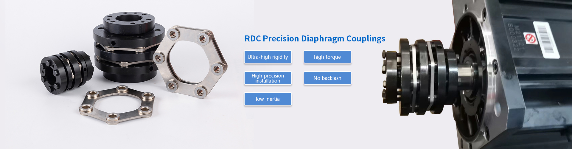
- Disc coupling (cople de membrana/disco): metallic disc pack transmits torque with near-zero backlash; handles up to 500,000 Nm in heavy designs; ideal for servo drives, compressors, and high-speed turbomachinery where a flexible coupling overview shows disc designs outperforming elastomeric alternatives above 6,000 rpm.
- Gear coupling (cople de dientes): involute-tooth meshing; high torque density (up to 2,000,000 Nm); tolerates up to 2° angular misalignment; requires periodic lubrication — a maintenance liability in food-processing environments.
- Grid coupling (cople de grilla): spring-steel grid element seated in grooved hubs; excellent shock absorption; common in conveyor and crusher drives.
Coupling connectors in the flexible category also include oldham, Schmidt, and Bellows types for instrument-grade and low-torque precision applications, though these represent a smaller share of Mexico's industrial market.

Fluid couplings: how they work and when to use them
A fluid coupling transmits torque entirely through a hydraulic working fluid — typically turbine oil — circulating between an impeller (pump wheel) connected to the driver and a runner (turbine wheel) connected to the driven machine. There is no mechanical link between the two halves, which is both the greatest advantage and the most significant limitation of this coupling family.
Operating principles and slip characteristics
The torque transmitted is proportional to the square of the impeller speed and the fifth power of the working-circuit diameter (Föttinger's law). At startup, slip (the speed difference between impeller and runner) is high — sometimes 100% — which means the motor accelerates under reduced load, dramatically cutting inrush current. As the driven machine reaches operating speed, slip falls to 2–4% in normal running conditions. Think of it like a hydraulic torque converter in an automatic gearbox: smooth, forgiving, and inherently self-limiting under overload.
Variable-fill and constant-fill variants
Constant-fill fluid couplings are fixed-capacity units suited to belt conveyors, bucket elevators, and fan drives where startup torque control is the primary goal. Variable-fill designs allow continuous adjustment of the oil volume — and therefore the transmitted torque — via a scoop tube mechanism, enabling speed control over a 60–97% slip range. These units are widely used in Mexican cement and mining operations as low-cost alternatives to variable-frequency drives on motors above 200 kW.
"Fluid couplings remain the most cost-effective soft-start solution for high-inertia loads above 150 kW where VFD installation is impractical due to harmonic distortion constraints or hazardous area classifications." — IMARC Group, Mexico Industrial Couplings Market Report 2026
Magnetic couplings: the emerging fluid-free alternative
Magnetic couplings transmit torque across an air gap using permanent magnets, eliminating both mechanical contact and hydraulic fluid. They provide inherent overload protection through magnetic slip and are increasingly specified for hygienic or hermetically sealed applications. According to 2026 industry data, magnetic coupling units are growing at approximately 10% annually in Mexico, driven by pharmaceutical and chemical sector demand. They remain expensive — typically 3–5× the cost of an equivalent jaw coupling — but their zero-maintenance profile is compelling in hard-to-access installations.
Head-to-head comparison: data table and key metrics
The table below consolidates real-world performance parameters for the most common coupling for machinery types encountered in Mexican industrial facilities. All torque and speed figures reflect standard catalog ratings; actual service limits depend on shaft diameter, service factor, and thermal conditions.
| Coupling type | Torque range (Nm) | Max speed (rpm) | Angular misalign. | Radial misalign. (mm) | Backlash | Maintenance | Approx. cost index |
|---|---|---|---|---|---|---|---|
| Rigid sleeve | 5 – 50,000 | 3,600 | 0° | 0 | Zero | None | 1× |
| Jaw (elastomeric) | 5 – 4,000 | 6,500 | 1° | 0.25 | Low | Spider replace 2–3 yr | 1.2× |
| Gear coupling | 100 – 2,000,000 | 5,000 | 2° | 0.75 | Medium | Lube every 6–12 mo | 2× |
| Disc coupling | 10 – 500,000 | 30,000 | 0.5° | 0.10 | Near zero | Inspect disc pack annually | 3× |
| Fluid coupling (constant-fill) | 100 – 800,000 | 1,800 | N/A (flex. mounts) | N/A | High (slip) | Oil change 1–2 yr | 5× |
| Magnetic coupling | 1 – 15,000 | 6,000 | N/A (air gap) | N/A | High (slip) | None | 8× |
Cost index is relative to a standard rigid sleeve coupling of equivalent bore size. Figures are indicative ranges compiled from manufacturer catalogs and BIOSA México field data, 2025–2026.
Coupling selection guide: step-by-step process
A systematic coupling selection guide prevents the two most common errors: selecting by shaft diameter alone, and skipping the service-factor calculation. The following process applies to any of the types of couplings reviewed above.
- Define rated torque (TN): Calculate from motor power (kW) and speed (rpm) using TN = 9,550 × P / n. Example: a 75 kW motor at 1,480 rpm yields TN = 484 Nm.
- Apply the service factor (KA): Multiply TN by the appropriate AGMA service factor — 1.25 for uniform load, up to 2.5 for heavy shock (crushers, shredders). Required coupling torque = TN × KA.
- Confirm shaft diameter compatibility: The coupling bore must accommodate the shaft diameter with the correct fit tolerance (H7/k6 for most industrial couplings). Never force a bore undersized — it creates residual stress that promotes fatigue cracking.
- Measure actual misalignment: Use a dial indicator or laser alignment tool to quantify angular and radial offset. Cross-reference with the coupling's rated misalignment capacity. If offset exceeds the coupling's limit, correct alignment first — do not select a "more tolerant" coupling as a workaround.
- Evaluate operating environment: Temperature range, chemical exposure, explosive atmosphere classification (ATEX Zone 1 or 2), and hygiene requirements all narrow the material and design options available.
- Select coupling type by application scenario:
- Mining / crusher drives → gear coupling or variable-fill fluid coupling
- Cement kiln fan / conveyor → constant-fill fluid coupling or grid coupling
- Food and beverage line → stainless jaw coupling or magnetic coupling (washdown)
- Water pump (NOM-001-SEDE) → jaw or disc coupling, API 610 compliant where required
- CNC machine tool → disc or bellows coupling (zero backlash)
- Verify speed (nmax) and dynamic balance grade: High-speed applications above 3,000 rpm require couplings balanced to ISO 1940-1 G2.5 or better. Fluid couplings have inherent speed limits due to centrifugal oil pressures — confirm with the manufacturer above 1,500 rpm.
Laser alignment procedure after installation
Even the most tolerant flexible coupling degrades prematurely if installed without proper alignment. Laser alignment is the 2026 industry standard for all industrial shaft connectors above 15 kW. Set the reverse-indicator method targets to: angular offset ≤ 0.05 mm/100 mm; radial offset ≤ 0.05 mm for speeds above 1,500 rpm, ≤ 0.08 mm below 1,500 rpm. Torque all fasteners to the manufacturer's specified value using a calibrated torque wrench. Recheck alignment after the first thermal cycle (8 hours of operation) since thermal growth on motor and pump housings commonly shifts shaft centerlines by 0.03–0.12 mm.
Which coupling is right for a conveyor drive in a Mexican mine?
For heavy-inertia belt conveyor drives above 200 kW in Mexican mining operations (Sonora, Zacatecas), a constant-fill or variable-fill fluid coupling is the prevailing choice. It limits peak torque during starting to 150–180% of rated torque, protecting the belt, gearbox, and motor simultaneously. Gear couplings are used on the gearbox output shaft where precise torque transmission and high misalignment tolerance combine. This dual-coupling architecture is the dominant configuration in Grupo México and similar operations, based on equipment inspection data from 2025.
Failure diagnosis and real-world cases
Understanding failure modes is inseparable from understanding types of couplings. Each design fails in a characteristic way, and recognizing the pattern early prevents catastrophic drive-train damage.
Common failure modes by coupling type
Elastomeric jaw coupling — spider aging: The polyurethane or Hytrel spider element hardens and cracks with age, heat cycling, and oil contamination. Early warning: increased torsional vibration at 2× running frequency. Actual case: a water treatment plant in Guadalajara experienced repeated jaw coupling failures every 8–10 months. Root cause analysis revealed pump bearing seal leakage contaminating the spider with process water — not misalignment as initially assumed. Switching to a closed-hub jaw design with an oil-resistant NBR spider extended service life to over 24 months.
Gear coupling — tooth flank wear: Inadequate or contaminated grease causes fretting corrosion on the involute teeth. Vibration signature shows sidebands around mesh frequency. A cement plant in Monterrey reported gearbox input shaft failures tracing back to gear coupling tooth wear — the lubrication interval had been extended from 6 to 18 months during a cost-reduction initiative. Restoring the 6-month schedule and switching to a synthetic coupling grease (NLGI 1.5) eliminated the failures within one maintenance cycle.
Fluid coupling — oil overheating and fusible plug activation: If the driven machine stalls (jammed conveyor, locked pump), the fluid coupling absorbs all motor power as heat. Most units incorporate a fusible plug that melts at 120–145°C, draining the oil and preventing fire. The coupling must then be refilled and the root cause of the stall corrected before restart. This is a feature, not a defect — but it is frequently misdiagnosed as coupling failure in field reports.
Disc coupling — fatigue cracking: Excessive misalignment beyond the rated angular limit generates cyclic bending stress in the disc pack. Cracks typically initiate at the bolt holes. Inspection with a bright light and magnifier every 12 months is sufficient to catch early-stage cracking before catastrophic separation occurs.
Why do couplings keep failing even after replacement?
This is the question plant engineers in Mexico most frequently raise during troubleshooting sessions. The answer is almost always the same: the coupling is absorbing a system problem rather than causing one. Persistent misalignment, foundation resonance, cavitating pumps, or thermally expanding piping systems all impose cyclic loads that exceed any coupling's designed capacity. Replacing the coupling without addressing the root cause is — to use a direct analogy — like replacing a blown fuse repeatedly instead of finding the short circuit.
Mexico compliance, sourcing, and 2026 market outlook
Sourcing industrial shaft connectors and power transmission couplings in Mexico involves navigating a layered compliance environment alongside practical supply-chain realities that differ significantly from the US or European markets.
Applicable standards and certifications
Mexico's primary electrical installation standard, NOM-001-SEDE-2012 (and its 2022 revision), governs equipment in classified areas and references ANSI/AGMA 9000 for coupling quality grades. For pump applications in the oil and gas sector, API 610 (centrifugal pumps) mandates disc or flexible-element couplings with specific dynamic balance and spacer-piece requirements. ATEX certification (Directive 2014/34/EU, recognized by México's SEMARNAT technical requirements for hazardous environments) is required for fluid couplings installed in Zone 1 or Zone 2 areas — a frequent oversight in Mexican petrochemical and paint manufacturing facilities. Always request the ATEX certificate and the Declaration of Conformity from the supplier, not just a product data sheet.
Pricing, lead times, and local sourcing realities
Standard jaw couplings in bore sizes 19–50 mm are widely stocked by industrial distributors in Monterrey, Guadalajara, and Mexico City at MXN 350–1,800 per unit (2026 reference prices). Gear couplings and disc couplings above 500 Nm typically require import or custom manufacture, with lead times of 6–14 weeks from European or Asian suppliers. Variable-fill fluid couplings above 300 kW are almost exclusively imported; budget 10–16 weeks and 15–30% import duty and logistics surcharge on the CIF value.
The 2026 nearshoring wave — driven by automotive OEM relocation to Coahuila, Nuevo León, and Guanajuato — has tightened local inventory on mid-range flexible couplings. Procurement teams are advised to maintain at least one full coupling set (hubs plus element) as critical spare stock. The Mexican industrial couplings market was valued at approximately USD 45 million in 2025 and is projected to reach USD 127 million by 2034, expanding at a CAGR of 11.97% (IMARC Group, 2026 report). That growth rate signals increasing local manufacturing capability, but import dependence for precision components will persist through at least 2028.
2026 technology trends: smart couplings and magnetic drive growth
Sensor-integrated couplings — units with embedded strain gauges or wireless torque telemetry — are entering Mexican automotive and food-processing plants as part of Industry 4.0 upgrades. While still a small share of total coupling sales, these devices enable real-time condition monitoring without additional instrumentation on the drive shaft. Magnetic coupling penetration is growing at ~10% annually, particularly in pharmaceutical manufacturing clusters in Jalisco and chemical processing in Veracruz, where hermetic sealing and zero-maintenance operation justify the higher unit cost.
Frequently asked questions
Frequently asked questions
Q: What is the most important factor when choosing between types of couplings?
A: Required torque with service factor applied is the primary criterion — not shaft diameter. After confirming torque, evaluate misalignment type and magnitude, operating speed, environmental conditions, and maintenance access. Matching all five parameters to the coupling's rated specifications is the foundation of a reliable selection.
Q: Can a flexible coupling compensate for poor shaft alignment?
A: No. Flexible couplings tolerate small, unavoidable residual misalignment after proper alignment — they are not designed to correct gross offset. Relying on coupling flexibility instead of aligning the machine accelerates wear on the coupling element, bearings, and seals, ultimately costing far more than the alignment procedure itself.
Q: When does a fluid coupling make more sense than a variable-frequency drive (VFD)?
A: For high-inertia loads above 150 kW in hazardous or remote locations, fluid couplings often offer lower total installed cost, simpler harmonic management, and greater robustness under dusty or high-humidity conditions. VFDs provide more precise speed control and energy recovery but require clean power, EMC shielding, and trained maintenance personnel.
Q: What certifications should I require for couplings in a Mexican hazardous area installation?
A: Request ATEX certification (Category 2G or 3G as appropriate), the EU Declaration of Conformity, and confirmation that the coupling meets ANSI/AGMA 9000 or API 610 as applicable. For electrical area classification under NOM-001-SEDE, verify that the supplier's documentation references the specific zone and temperature class of your installation.
Q: What is the typical replacement interval for a jaw coupling spider element in industrial use?
A: Under normal conditions — moderate shock, clean environment, correct alignment — a polyurethane spider element lasts 2–3 years. In high-shock or high-temperature applications, or where oil contamination is present, inspect every 12 months and replace at the first sign of cracking or compression set. Keeping spare spider elements on-site eliminates unplanned downtime during shift changes.
Conclusion: making the right choice for your application
The choice between fluid couplings and mechanical couplings is never arbitrary — it flows directly from the physics of the application. Rigid couplings deliver precision and simplicity where alignment is controlled. Flexible mechanical couplings — jaw, disc, gear, grid — cover the vast majority of industrial drive-train scenarios with proven reliability. Fluid couplings solve the soft-start and overload-protection challenge in high-inertia, high-power applications where no mechanical alternative can match their performance-to-cost ratio. And magnetic couplings are carving out a growing niche wherever hermetic sealing or zero-maintenance operation is non-negotiable.
For engineers and procurement teams operating in Mexico in 2026, the practical implication is this: anchor your selection in the torque calculation, verify misalignment with measurement rather than assumption, insist on the correct compliance documentation, and treat the coupling as a system component rather than an isolated spare part. The types of couplings available today cover every conceivable industrial need — the competitive advantage lies in selecting the right one, installing it correctly, and maintaining it on schedule.
Consult immediately
If you are interested in our products, please leave your email address, and we will get in touch with you as soon as possible. Thank you!
Kunshan Haozong Transmission Technology Co., Ltd.
Contact: Manager Liu 13372152786 (WeChat)
Email: liu@hz-coupling.com
Address: Room A5-304, No. 18 Jinxing Road, Huaqiao Town, Kunshan City, Jiangsu Province

Scan the mobile website