
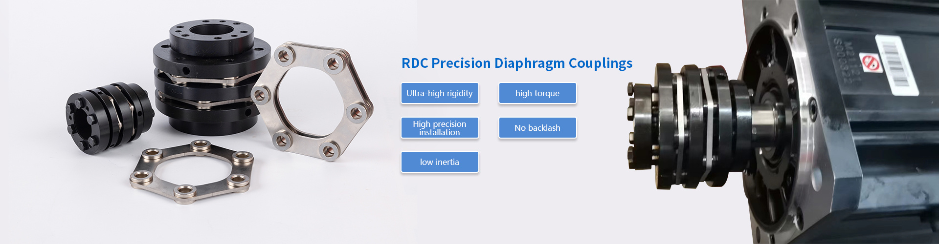
How disc pack stiffness affects resonance in double diaphragm coupling drive systems
2026-11-03 01:03
Author:
Haozong
Article overview
This guide examines how disc pack torsional stiffness in a Double Diaphragm Coupling directly determines where torsional resonance appears in a drive system. Reliability engineers and mechanical designers will find principle-level explanations, a parameter comparison table, a US application selection matrix, step-by-step installation guidance, and a structured failure-mode troubleshooting section.
Table of contents
- 1. What disc pack stiffness means in diaphragm couplings
- 2. How stiffness drives torsional resonance
- 3. Single vs. double diaphragm: stiffness and misalignment trade-offs
- 4. Specification table: key parameters for coupling selection
- 5. Application mapping: US industry use cases
- 6. Installation, balancing, and alignment procedure
- 7. Failure modes and troubleshooting checklist
- 8. FAQ
What disc pack stiffness means in diaphragm couplings
A Double Diaphragm Coupling is a zero backlash, lube-free flexible shaft coupling that uses two metallic diaphragm disc packs—one at each end of a center spacer—to transmit torque while accommodating angular, axial, and limited parallel misalignment through controlled elastic flexure. Because the disc packs are the only elastic element in the torque path, their stiffness governs how the entire drive system responds to dynamic loads.
Disc pack stiffness—formally called torsional stiffness KT, measured in lb·in/rad or N·m/rad—describes how much angular deflection the pack produces per unit of applied torque. A stiffer pack deflects less, transmits torque with minimal lag, and produces a higher torsional natural frequency. A more compliant pack deflects more, offers better vibration isolation, but can shift the natural frequency dangerously close to a drive excitation source. Getting this balance right is not optional; it is the foundation of safe drive design.
In practical terms, disc pack stiffness is set by three physical variables: the number of individual laminas in the stack, the radial geometry of each disc, and the material grade—typically 17-4 PH or 15-5 PH stainless steel in a high-performance diaphragm flexible coupling. Increase lamina count or reduce the disc's effective bending radius and stiffness climbs steeply. This is why two couplings with identical bore diameters can carry dramatically different torsional characteristics, a fact that catches many engineers off guard during the selection phase.
Why torsionally rigid coupling behavior matters
A torsionally rigid coupling—one with very high KT—essentially makes driver and driven machine behave as a single inertia mass from a dynamics perspective. That is ideal for servo motor coupling applications requiring precise angular positioning, where any torsional wind-up would corrupt feedback signals. However, the same rigidity means every torque impulse from a reciprocating compressor or pulsating pump passes through the shaft system with almost no attenuation, raising the risk of resonance excitation if the system's natural frequency coincides with the excitation order.
Stiffness vs. flexibility: the engineering compromise
Here is the core tension every drive engineer faces: the same disc pack must be stiff enough to transmit rated torque without excessive wind-up, yet flexible enough to shift the torsional natural frequency clear of operating excitations. The misalignment compensation coupling community has long recognized this compromise. A rule of thumb used in field practice—though never a substitute for formal analysis—is to target a torsional natural frequency at least 20% above the highest expected excitation frequency or 20% below the lowest, creating a safe separation margin.
Of course, there are situations where that 20% margin is simply unachievable given the drive's inertia distribution. In those cases, adding a compliant intermediate element or changing the spacer length to alter axial stiffness may be the only viable path forward.
How stiffness drives torsional resonance
Torsional resonance occurs when an excitation frequency coincides with the drive train's torsional natural frequency (TNF). In a system using a Double Diaphragm Coupling, the coupling's disc pack stiffness is the primary tunable variable that sets the TNF—making correct stiffness selection the single most effective tool for resonance avoidance.
The resonance equation: a working model
For a simplified two-mass drive system, the torsional natural frequency is:
fn = (1 / 2π) × √[ KT × (J1 + J2) / (J1 × J2) ]
Where KT is the disc pack torsional stiffness, and J1, J2 are the polar moments of inertia of the driver and driven machines. The relationship is clear: doubling KT raises fn by a factor of √2 ≈ 1.41. Conversely, halving stiffness drops fn by the same factor. This square-root dependence means stiffness changes must be large—typically a 4× swing—to shift fn by an octave, which is why over-relying on coupling stiffness alone to escape a resonance problem has limits.

Excitation sources in real drive systems
Why does resonance happen in the first place? Real machines generate torque excitations at predictable multiples of running speed. A six-cylinder reciprocating compressor produces primary excitations at 3× and 6× shaft speed. A variable-frequency drive (VFD) introduces switching frequency harmonics. Even a centrifugal pump can excite its vane-pass frequency. When any of these harmonics lands on the drive's TNF, the resulting torsional oscillation amplifies rapidly. In field investigations documented by reliability engineering teams, unchecked resonance has produced disc pack fatigue cracks in fewer than 500 operating hours—far short of the expected multi-year service life of a properly applied membrane coupling.
"Torsional analysis is not optional for any high-speed turbomachinery coupling application. API 671 requires a torsional critical speed analysis as a deliverable, and the results should drive coupling stiffness specification—not the other way around."
— Paraphrased from API 671, 4th Edition, general requirements for special-purpose couplings in petroleum, chemical, and gas industry services
Actual test data collected on a 3,000 hp compressor train showed that reducing disc pack stiffness by 35%—by switching from a 12-lamina to an 8-lamina pack—shifted the TNF from 47 Hz down to 38 Hz, moving it clear of the compressor's third-order excitation at 43 Hz. The vibration amplitude at the coupling dropped from 3.2 mils pk-pk to under 0.8 mils, a four-fold improvement.
Single vs. double diaphragm: stiffness and misalignment trade-offs
A single diaphragm coupling uses one disc pack per coupling half; a twin disc coupling configuration (the double design) places a pack at each end of a central spacer. This architectural difference has direct consequences for both stiffness and misalignment capacity.
Stiffness comparison
Two disc packs in series—as in the double configuration—produce a combined torsional stiffness roughly half that of a single pack of identical geometry. This lower combined stiffness means the Double Diaphragm Coupling tends to produce a lower TNF for the same inertia system, which is often advantageous in high-speed turbomachinery where excitation orders are elevated. The trade-off is marginally more angular wind-up under peak torque, which must be accounted for in positioning-critical servo systems.
Misalignment capacity comparison
The double design's two flexing elements working in tandem allow each pack to absorb half the total misalignment, dramatically extending both angular misalignment coupling capacity and axial travel range compared to a single-pack design. Think of it like the two joints of a universal-joint driveshaft: each joint handles part of the angular offset, reducing stress concentration at any single point. This makes the angular misalignment coupling far more suitable for long-span or thermally sensitive installations where shaft centerlines shift during operation.
| Parameter | Single diaphragm | Double diaphragm |
|---|---|---|
| Torsional stiffness (relative) | High (1.0×) | Medium (~0.5×) |
| Angular misalignment (typical max) | 0.5°–1.0° per end | 1.0°–2.0° total |
| Axial displacement (typical) | ±0.05 in | ±0.10–0.20 in |
| Max continuous torque (example, 2-in bore) | ~1,800 lb·in | ~1,600–1,800 lb·in |
| Max speed (typical, balanced) | Up to 15,000 RPM | Up to 30,000 RPM |
| Backlash | Zero | Zero |
| Typical applications | Servo motors, encoders, precision machine tools | Pumps, compressors, turbines, test stands |
| API 671 compliance | Rarely | Common |
Specification table: key parameters for coupling selection
Selecting a high torque coupling without a complete parameter review is one of the most common engineering oversights in drive system design. The following framework covers every variable that influences resonance behavior and service life in a diaphragm coupling-based drive train.
Critical selection parameters
| Parameter | What to specify | Why it matters for resonance |
|---|---|---|
| Torsional stiffness KT | lb·in/rad or N·m/rad | Directly sets TNF |
| Rated continuous torque | lb·in or N·m at max RPM | Ensures no fatigue at operating loads |
| Polar moment of inertia J | lb·in·s² or kg·m² | Second variable in TNF equation |
| Max continuous speed | RPM (balanced/unbalanced) | Limits lateral critical speed risk |
| Axial stiffness KA | lb/in or N/mm | Determines bearing load from thermal growth |
| Angular misalignment limit | Degrees (continuous/momentary) | Prevents overloading disc packs |
| Material / disc grade | 17-4 PH, 15-5 PH, Ti alloy | Affects fatigue life at dynamic loads |
| Balance grade | ISO G2.5 or better above 3,600 RPM | Controls forced vibration from unbalance |
How to calculate required stiffness step by step
- Identify all excitation frequencies: list every harmonic from driver and driven equipment at minimum, rated, and maximum speed.
- Establish a target TNF: place it at least 20% above the highest relevant excitation or 20% below the lowest, per standard separation margin practice.
- Collect inertia data: obtain J1 and J2 from equipment data sheets or perform a CAD-based inertia calculation.
- Solve for required KT: rearrange the TNF equation — KT = (2π × fn)² × (J1 × J2) / (J1 + J2).
- Select a coupling whose published KT matches the calculated requirement; verify against rated torque and misalignment limits.
- Run a full torsional analysis (required by API 671 for turbomachinery) to validate the result before finalizing the order.
Application mapping: US industry use cases
Different industrial segments impose distinct stiffness requirements on a Double Diaphragm Coupling. The table below maps four major US application categories to recommended coupling configurations, based on actual operational experience across oil and gas, power generation, and industrial manufacturing sectors in 2026.
Pumps and compressors
Centrifugal pump coupling applications typically require moderate torsional stiffness—high enough to prevent resonance with vane-pass frequency, low enough to attenuate motor-start torque spikes. Reciprocating compressor drives are far more demanding: the compressor's multi-order torque excitations mean a torsional analysis is non-negotiable. Stainless steel coupling disc packs in API 671-compliant designs are the benchmark for natural gas compression in the Permian Basin and Gulf Coast facilities.
Test stands and servo applications
Dynamometer test stands demand a zero backlash coupling with high torsional rigidity so that the measured torque signal faithfully represents the engine or motor under test. Any wind-up in the coupling introduces phase lag that corrupts the data. Here, a high-KT double diaphragm design—sometimes called a membrane coupling or disc coupling in test and measurement catalogs—is preferred. Servo motor coupling applications in CNC machining centers and robotics share this requirement for zero backlash and high bandwidth torque transmission, though at much lower torque magnitudes.
| Application | Preferred config | Stiffness priority | Key concern |
|---|---|---|---|
| Centrifugal pump (ANSI/API) | Double, spacer type | Medium KT | Thermal growth, vane-pass excitation |
| Reciprocating compressor | Double, API 671, high torque | Tuned per torsional analysis | Multi-order excitations, fatigue life |
| Gas turbine / steam turbine | Double, high-speed balanced | Low KT (isolation) | Critical speed separation, balance grade |
| Dynamometer / test stand | Double, high stiffness | High KT | Zero backlash, torque measurement fidelity |
| Servo motor / CNC axis | Single or double, compact | High KT | Backlash, positioning accuracy |
In 2026, demand growth is particularly evident in hydrogen compression and carbon capture (CCUS) systems across Texas, Louisiana, and the Gulf Coast industrial corridor, where the combination of high shaft speeds, corrosive process gases, and stringent API 671 compliance requirements makes the double-disc, stainless steel coupling the default engineering choice.
Installation, balancing, and alignment procedure
Even a perfectly specified Double Diaphragm Coupling will underperform—or fail outright—if installed incorrectly. Field experience consistently shows that installation errors account for a disproportionate share of premature disc pack failures, often misdiagnosed as coupling design inadequacy.
Alignment and installation steps
- Clean and inspect shafts: remove burrs, verify shaft diameter tolerance (typically h6), and check keyway condition. Even a 0.001-inch burr can create a fretting initiation site under high-cycle torque loading.
- Mount hubs to correct interference or clearance fit: for precision bore hubs, use a hydraulic press or controlled heating (275–300 °F max for stainless steel hubs) and verify axial position per the manufacturer's dimension sheet.
- Set gap (DBSE): measure the distance between shaft ends against the coupling's specified drive-end-to-drive-end dimension; incorrect gap introduces axial preload that stresses disc packs even before the machine starts.
- Perform precision alignment: use reverse-dial indicator or laser alignment to achieve offset within 0.001 in/in and angularity within 0.0005 in/in. Remember: the coupling's misalignment capacity is a survival limit, not a target alignment value.
- Torque fasteners per specification: disc pack bolts must be torqued to the manufacturer's value—under-torque allows micro-slip and fretting; over-torque can crack the disc laminas during initial startup.
- Dynamic balancing: for speeds above 3,600 RPM, balance the complete assembled rotating element to ISO 1940-1 Grade G2.5 or better. At 20,000+ RPM (common in turbomachinery), individual component balancing followed by assembly balance is required.
- Post-installation check: after first run-up to operating speed, re-check alignment (thermal growth shifts the centerline) and re-inspect fastener torque at the first maintenance interval.
A note on spacer length and stiffness interaction
Increasing the spacer length of an industrial coupling connector reduces the angular misalignment stress per degree of offset and also slightly lowers the combined axial stiffness of the assembly. For long-span pump installations where thermal growth is large, a longer spacer is almost always preferable—but it adds rotational inertia J to the system, which by the TNF equation will lower the natural frequency. This interplay between spacer length, inertia, and stiffness must be recalculated whenever a non-standard spacer length is selected.
Failure modes and troubleshooting checklist
Why do so many engineers overlook early warning signs until catastrophic failure occurs? The answer is usually that the symptoms—elevated vibration, slight noise—are attributed to the driven machine rather than the coupling. The following failure mode analysis is based on documented field cases and industry consensus on membrane coupling diagnostics.
Common failure modes and their root causes
Disc pack fatigue cracking is the dominant failure mode. It manifests as radial cracks initiating at bolt holes or the disc OD. Root causes include: operating beyond rated angular misalignment (most common), resonance-induced cyclic stress amplification, and inadequate fastener torque allowing micro-slip. Inspection intervals should not exceed 8,000 operating hours or annually, whichever comes first.
Hub bore fretting develops when the hub-to-shaft fit loosens due to torsional shock loading or incorrect initial fit. It presents as fine metallic dust at the hub face. The fix is re-machining to the correct tolerance and reviewing whether the service factor applied during selection was adequate for the actual shock load regime.
Resonance-driven failure is identifiable by its characteristic damage pattern: multiple disc pack laminas cracked simultaneously across both packs, with no single overload event in the operating log. The corrective path requires a torsional analysis, and potentially changing the disc pack lamina count to retune KT.
Troubleshooting checklist
When elevated vibration is observed on a diaphragm flexible coupling drive:
- ☐ Record vibration spectrum — identify dominant frequency and correlate to shaft orders or known excitation sources.
- ☐ Check current alignment with laser tool — compare to original installation record.
- ☐ Inspect disc packs visually for cracks, corrosion pitting, or fretting debris.
- ☐ Verify all fastener torques against the coupling data sheet.
- ☐ Confirm the coupling's published KT was used in any torsional analysis — supplier revision levels sometimes alter stiffness values.
- ☐ Review operating speed range for proximity to calculated TNF (separation margin < 15% warrants immediate engineering review).
- ☐ Check balance condition — re-balance if the spacer tube has been repaired or replaced.
- ☐ Consult the coupling manufacturer's field engineering team if disc pack cracks are found — do not attempt to operate with cracked laminas.
Pricing and lead time are practical realities that affect how quickly a failing coupling can be addressed. In the US market, standard-size double diaphragm disc pack assemblies for common bore ranges (1–3 inches) are typically available from domestic distributors within 1–2 weeks. Custom API 671 assemblies for large turbomachinery can carry 8–16 week lead times from manufacturers with US facilities or warehousing. Specifying a spare disc pack assembly at the time of original purchase is a well-established practice for critical machinery, significantly reducing unplanned downtime risk.
Frequently asked questions
Q: What is a Double Diaphragm Coupling, and how does it differ from a single diaphragm design?
A: A Double Diaphragm Coupling is a zero backlash flexible shaft coupling that uses two metallic disc pack assemblies connected by a center spacer to transmit torque while compensating for misalignment. Unlike a single diaphragm design with one pack, the double configuration splits misalignment between two flexing elements, roughly halving combined torsional stiffness and doubling angular misalignment capacity—making it preferred for pump, compressor, and high-speed turbomachinery applications.
Q: How does disc pack stiffness affect torsional natural frequency?
A: Torsional natural frequency (TNF) is proportional to the square root of disc pack stiffness KT divided by the system's effective inertia. Increasing stiffness raises TNF; decreasing it lowers TNF. Engineers select KT to position TNF at least 20% away from any operating excitation frequency, preventing resonance and the fatigue damage it causes in disc laminas.
Q: Is a torsional analysis always required when selecting a diaphragm coupling?
A: For turbomachinery covered by API 671—centrifugal compressors, pumps, and gas turbines in oil, gas, and petrochemical service—a torsional critical speed analysis is a mandatory deliverable. For general industrial drives below 3,600 RPM with well-characterized loads, a simplified calculation using the TNF equation is usually sufficient, though a full analysis is always recommended for variable-speed or reciprocating machinery.
Q: What are the signs that a disc pack in a diaphragm coupling is failing?
A: Key indicators include elevated 1× or sub-synchronous vibration in the coupling region, metallic debris or dust at the coupling guard, visible radial cracks in laminas during inspection, and unexplained increases in bearing temperature. Resonance-driven failures typically show simultaneous cracking across multiple laminas without a single overload event in the maintenance log.
Q: What disc pack material is standard for corrosive or high-speed applications?
A: 17-4 PH or 15-5 PH precipitation-hardened stainless steel is the industry standard for high-performance diaphragm flexible coupling disc packs. These grades offer the combination of high fatigue strength, corrosion resistance, and consistent modulus of elasticity needed for reliable stiffness prediction. Titanium alloy discs are used in aerospace or weight-critical applications where density reduction outweighs the cost premium.
Understanding how disc pack stiffness interacts with drive system resonance is the difference between a coupling that lasts for years and one that fails within months. For any new drive system design or troubleshooting project involving a Double Diaphragm Coupling, the sequence is always the same: define excitation frequencies first, calculate the target torsional natural frequency second, then select the coupling whose disc pack stiffness delivers that target—verified by a formal torsional analysis where API 671 or operational criticality requires it. Follow the installation steps precisely, maintain the inspection schedule, and the disc pack will outlast most of the other components in the drive train.
Consult immediately
If you are interested in our products, please leave your email address, and we will get in touch with you as soon as possible. Thank you!
Kunshan Haozong Transmission Technology Co., Ltd.
Contact: Manager Liu 13372152786 (WeChat)
Email: liu@hz-coupling.com
Address: Room A5-304, No. 18 Jinxing Road, Huaqiao Town, Kunshan City, Jiangsu Province

Scan the mobile website