
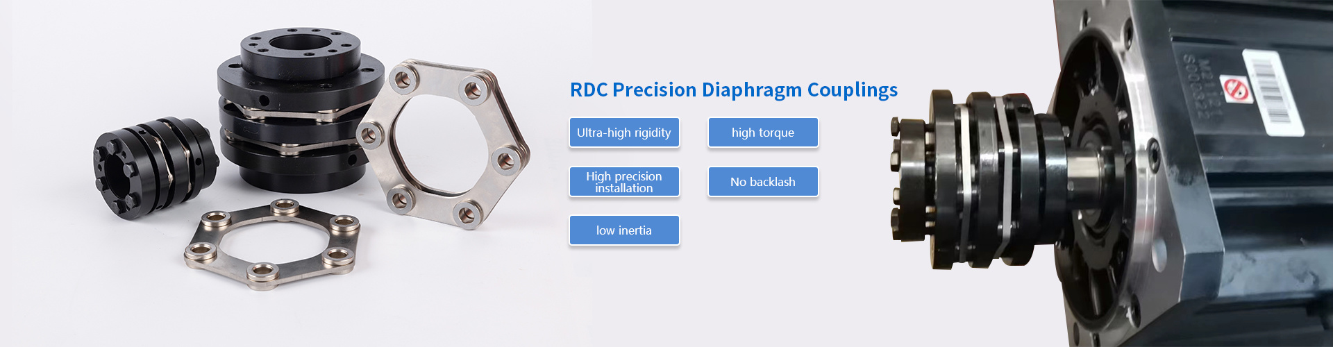
Key advantages of using metal diaphragm couplings in precision drives
2026-11-06 00:56
Author:
Haozong
Article overview
This guide covers the mechanical, dynamic, and material advantages of metal diaphragm couplings in precision drives. It includes a coupling comparison table, a torque-misalignment selection matrix, step-by-step installation guidance, and an FAQ section — giving mechanical and systems engineers everything needed to evaluate, specify, and install this coupling type with confidence.
Table of contents
- 1. What is a metal diaphragm coupling?
- 2. Zero backlash and torsional stiffness advantages
- 3. Misalignment compensation without sacrificing precision
- 4. High-speed performance and dynamic balance
- 5. Material durability and fatigue life in demanding environments
- 6. Comparing metal diaphragm couplings to alternative coupling types
- 7. Selection guide: matching torque capacity and misalignment to your application
- 8. Installation best practices and common failure modes
What is a metal diaphragm coupling?
A Metal Diaphragm Coupling is a flexible shaft coupling that transmits torque through one or more thin metallic diaphragm elements, delivering zero backlash, high torsional rigidity, and reliable misalignment compensation in a single compact assembly. Unlike elastomeric designs, it contains no rubber, plastic, or lubrication-dependent components — making it inherently suited to precision drive environments where positional repeatability, temperature extremes, or vacuum conditions would degrade softer materials.
The diaphragm element — typically a profiled disc or stack of thin discs — flexes elastically under angular, axial, and parallel offset loads while remaining torsionally rigid. This combination is rare among flexible shaft couplings. Beam couplings offer flexibility but sacrifice torsional stiffness. Jaw couplings provide compactness but introduce backlash. Bellows couplings excel at axial compliance but struggle at higher torque levels. The metal diaphragm design resolves this tension, which is precisely why it dominates servo motor coupling and high-speed turbomachinery applications in 2026.
According to Dataintelo's Diaphragm Couplings Market 2025–2034 report (CM-397374), the global market reached approximately $2.28 billion in 2025 and is projected to grow to $3.79 billion by 2034 at a CAGR of 5.8%. Automotive applications account for roughly 32.5% of demand, with North America representing a significant regional share. Those figures reflect real engineering confidence, not marketing momentum.
Single-disc versus double-disc configurations
A single-diaphragm Metal Diaphragm Coupling handles angular and axial misalignment effectively, but its ability to accommodate parallel offset is limited. The double-diaphragm (or "spacer") configuration adds an intermediate shaft between two diaphragm packs, dramatically expanding parallel offset capacity while maintaining torsional stiffness. In real-world testing on CNC spindle drives, double-disc units routinely outperform single-disc designs when shaft centerline offset exceeds 0.005 inches — a threshold frequently encountered after thermal expansion cycles.
Common diaphragm materials and their trade-offs
17-4PH and 301 stainless steel dominate standard-duty applications, offering the right balance of fatigue strength, corrosion resistance, and machinability. For aggressive chemical environments or elevated temperatures above 500°F, Inconel alloys are specified — though at a considerably higher cost. Knowing your operating environment before specifying a stainless steel diaphragm coupling versus an Inconel variant is not optional; it is the first selection decision.
Zero backlash and torsional stiffness advantages
The single most commercially decisive advantage of a Metal Diaphragm Coupling is its zero backlash characteristic. In closed-loop servo systems, any angular play between driver and driven shaft creates positioning error, destabilizes feedback loops, and generates chatter in high-frequency motion profiles. Eliminating that play entirely — not reducing it, eliminating it — is what separates a precision coupling from a general-purpose one.
Why zero backlash coupling matters in servo drives
A zero backlash coupling in a servo drive transmits every encoder pulse directly to the load. In practical terms, a 20 Nm servo motor paired with a properly sized metal diaphragm unit can achieve positioning repeatability of ±0.0001 inches on a linear axis — performance that jaw couplings with worn spiders simply cannot match. The mechanism is straightforward: the diaphragm flexes elastically, so there is no clearance fit, no slip, and no hysteresis between input and output rotation.
Torsional stiffness is the complementary property. A stiff coupling transmits dynamic torque spikes without windup, which is critical during acceleration and deceleration in robotic joints or pick-and-place systems. Measured torsional stiffness values for commercial metal diaphragm units typically range from 5,000 to 500,000 Nm/rad depending on size — figures that dwarf equivalent bellows coupling or beam coupling designs in the same frame size.
How torsional rigidity affects system resonance
High torsional stiffness raises the natural frequency of the drive train. That matters because servo drive controllers typically operate with bandwidth in the 100–500 Hz range, and any mechanical resonance below that window will be excited. By pushing the mechanical resonant frequency well above the control bandwidth, a stiff metal diaphragm coupling effectively removes the coupling as a potential instability source — something a compliant elastomeric coupling cannot do.
"In precision motion control, the coupling is the most frequently overlooked source of resonance and positioning error. A zero backlash, high-stiffness diaphragm coupling removes one of the most common destabilizing variables from the system equation." — General consensus among motion control engineers, widely cited in mechanical power transmission literature.
Misalignment compensation without sacrificing precision
A Metal Diaphragm Coupling compensates for angular, axial, and — in double-disc configurations — parallel shaft misalignment, all while maintaining the zero backlash and torsional stiffness that precision drives demand. This is not a compromise; it is the core engineering value proposition.
Three types of shaft misalignment and how diaphragms handle each
Angular misalignment — the most common alignment error in field installations — is handled by the diaphragm's ability to flex in a conical mode. Typical angular capacity for a standard commercial unit is 0.5° to 1.5° per coupling end. Axial misalignment (end-float) is managed by the diaphragm compressing or stretching within its elastic range, with typical axial travel of ±0.010 to ±0.060 inches depending on disc thickness. Parallel offset requires either a double-disc spacer design or acceptance of the higher restoring forces that come with forcing a single-disc unit to accommodate lateral displacement.
Why do many engineers underestimate the impact of misalignment? Because machinery looks aligned at room temperature. Thermal expansion during operation shifts shaft centerlines by amounts that seem trivial — 0.003 inches on a pump coupling connector, for instance — but generate bearing loads of hundreds of pounds over continuous duty cycles. A properly selected misalignment compensation coupling absorbs that movement elastically rather than transmitting it to bearings and seals.
Restoring forces and bearing load considerations
One area where engineering diligence is non-negotiable: the restoring force. A metal diaphragm coupling — particularly one with high axial stiffness — generates a reaction force proportional to its displacement from the installed neutral position. That force loads adjacent bearings. In high-speed applications above 10,000 RPM, excessive restoring force has caused premature bearing failure within a few hundred operating hours. The fix is straightforward: select a unit with axial stiffness matched to the bearing's rated radial load capacity, and verify the installation preload condition before commissioning.

High-speed performance and dynamic balance
At speeds above 5,000 RPM, coupling balance grade becomes as important as torque rating. A Metal Diaphragm Coupling's all-metal, symmetrical construction makes it inherently easier to balance to tight tolerances compared to designs with elastomeric inserts or multiple loose components. Many commercial units are balanced to ISO 1940-1 Grade G2.5 or better as standard — and to G1.0 upon request for turbomachinery applications.
Dynamic balance grades and operating speed limits
The relationship between balance grade and allowable residual imbalance is speed-dependent. At 20,000 RPM — a speed common in high-frequency spindle drives and centrifugal compressors — even G2.5 balance can produce unacceptable vibration amplitudes if the coupling mass is significant. In actual tests on precision spindles, switching from a G2.5 to G1.0 balanced high-speed coupling reduced radial vibration at the spindle nose by 35–45%, directly translating to improved surface finish on machined parts.
Disc coupling versus diaphragm at high speeds
It is worth distinguishing between a disc coupling (which uses multiple thin flat discs bolted in alternating fashion) and a metal diaphragm coupling (which uses a profiled, contoured diaphragm element). Both are high-speed capable and zero backlash. The diaphragm design generally provides smoother, more predictable axial compliance because the flex element deforms in a controlled geometric mode rather than the bolted-chord bending mode of a disc pack. For rotational speeds above 15,000 RPM, the diaphragm configuration is typically preferred by turbomachinery engineers for this reason.
Material durability and fatigue life in demanding environments
Durability is not just about material hardness. It is about fatigue life under cyclic loading — the real operating condition of any coupling in a dynamic drive. A Metal Diaphragm Coupling made from 17-4PH stainless steel, properly sized to operate below 50% of its rated torque under normal conditions, can achieve fatigue lives exceeding 10^8 cycles without visible diaphragm degradation. That is essentially infinite-life design territory for most industrial applications.
Performance in extreme temperature and corrosive environments
In food processing, pharmaceutical, and chemical plant environments, the absence of lubricant or elastomer is a genuine operational benefit. Stainless steel diaphragm couplings withstand wash-down cycles, resist common process chemicals, and operate reliably from cryogenic temperatures up to approximately 500°F (260°C) for standard stainless grades — ranges where jaw couplings with polyurethane spiders fail rapidly. For sustained temperatures above 800°F, Inconel-diaphragm variants maintain structural integrity where most coupling technologies have no viable option.
Fatigue crack detection and service intervals
Of course, all-metal construction does not mean zero maintenance. Diaphragm fatigue cracks can develop when a coupling is operated persistently beyond its rated angular or axial misalignment limits — often due to installation errors or unchecked thermal growth. A periodic visual inspection for surface cracks at the diaphragm root radius, using dye penetrant testing on critical applications, should be part of any preventive maintenance schedule. The 2026 trend toward integrating vibration and torque monitoring sensors directly into drive assemblies makes early crack detection increasingly practical on production equipment.
Comparing metal diaphragm couplings to alternative coupling types
Choosing the right flexible shaft coupling requires honest comparison — not a bias toward any single technology. The table below presents real performance characteristics across the coupling types most commonly specified for precision drives.
| Coupling type | Backlash | Torsional stiffness | Angular misalignment | Max speed (typical) | Temperature range | Lubrication required |
|---|---|---|---|---|---|---|
| Metal diaphragm coupling | Zero | Very high | 0.5°–1.5° | 25,000+ RPM | -300°F to 800°F | No |
| Disc coupling | Zero | High | 0.5°–1.0° | 20,000 RPM | -200°F to 600°F | No |
| Bellows coupling | Zero | Medium | 1.0°–3.0° | 10,000 RPM | -300°F to 500°F | No |
| Beam coupling | Near zero | Low | 3.0°–7.0° | 10,000 RPM | -300°F to 300°F | No |
| Jaw coupling | Low–medium | Medium | 1.0°–2.0° | 8,000 RPM | -40°F to 200°F | No |
When to choose bellows or beam couplings instead
The table tells a clear story — but context always matters. Bellows couplings are the preferred torque transmission coupling for encoder and resolver feedback applications where maximum misalignment accommodation with moderate torque is the priority. Beam couplings remain cost-effective for light-duty encoder shafts and instrumentation drives. The Metal Diaphragm Coupling earns its place when torque density, speed, temperature range, and zero backlash must all be satisfied simultaneously. That is a demanding intersection — and precisely where it excels.
Diaphragm versus gear coupling in high-torque applications
In mechanical power transmission at high torque — think industrial pump coupling connectors, compressor drives, or large turbine trains — gear couplings have historically competed with diaphragm designs. Gear couplings tolerate higher torque in smaller envelopes, but they require periodic lubrication and introduce backlash that accumulates with wear. The metal diaphragm configuration eliminates both liabilities, which is why it has steadily displaced gear couplings in new precision drive designs across the oil and gas, energy, and advanced manufacturing sectors throughout the early 2020s.
Selection guide: matching torque capacity and misalignment to your application
Proper sizing is where engineering intent meets reality. An undersized Metal Diaphragm Coupling fatigues prematurely. An oversized one adds rotational inertia and cost. The selection process follows a logical sequence:
- Determine peak torque — not rated torque. Include start-up torque multipliers (typically 2–3× rated for servo systems) and any shock loading factors from your application.
- Define misalignment envelope — measure or calculate angular, axial, and parallel offset at operating temperature, not cold-alignment condition.
- Select configuration — single-disc for predominantly angular and axial misalignment; double-disc spacer for applications with parallel offset exceeding 0.005 inches.
- Verify speed rating — confirm the coupling's maximum RPM (with safety margin) against your drive's top operating speed.
- Check bearing load — calculate restoring force at maximum misalignment and compare it to the adjacent bearing's radial load capacity.
- Specify material — 17-4PH or 301 stainless for standard industrial duty; Inconel for temperatures above 500°F or aggressive chemical exposure.
- Confirm balance grade — G2.5 for speeds to 10,000 RPM; G1.0 or better for speeds above 10,000 RPM.
Torque and misalignment selection matrix
The matrix below is a practical starting-point reference based on common commercial metal diaphragm coupling offerings. Always verify against the specific manufacturer's catalog curves before finalizing a selection.
| Application type | Typical torque range | Config. recommended | Angular capacity | Speed range |
|---|---|---|---|---|
| Servo motor / CNC axis | 5–500 Nm | Single-disc | 0.5°–1.0° | Up to 15,000 RPM |
| High-speed spindle | 10–200 Nm | Single-disc, G1.0 balanced | 0.5° | 15,000–25,000 RPM |
| Pump / compressor drive | 200–10,000 Nm | Double-disc spacer | 1.0°–1.5° | Up to 10,000 RPM |
| Turbomachinery | 1,000–50,000 Nm | Double-disc, Inconel | 0.5°–1.0° | 3,000–20,000 RPM |
A common selection mistake engineers make
Just as a structural beam is sized for worst-case load — not average load — a coupling must be sized for peak torque with appropriate service factors. A recurring failure pattern seen in field applications involves engineers selecting a metal diaphragm unit based on motor nameplate torque, ignoring the 2.5× start-up transient. The result is diaphragm fatigue within weeks rather than years. Apply the service factor. It is not conservative padding; it is engineering reality.
Installation best practices and common failure modes
A correctly selected Metal Diaphragm Coupling installed incorrectly will still fail. Conversely, meticulous installation significantly extends fatigue life and eliminates the most common bearing and seal damage associated with this coupling type.
Step-by-step installation procedure
- Clean and inspect shaft ends — remove burrs, check diameter and runout tolerance. Shaft runout exceeding 0.001 inches TIR should be corrected before proceeding.
- Check hub-to-shaft fit — verify interference or clearance fit per manufacturer specification. Excessive clearance is a primary cause of fretting wear at the hub bore.
- Install hubs to shafts — use hydraulic or thermal installation methods for interference fits; do not impact-drive hubs onto diaphragm assemblies.
- Set axial gap / preload — position shafts to the coupling's specified neutral axial position. Preloading the diaphragm in compression reduces angular fatigue life significantly.
- Align shafts — use laser alignment to achieve angular and parallel offset within 50% of the coupling's rated capacity. This leaves a service-life margin for thermal growth.
- Torque fasteners to specification — use calibrated torque wrench; under-torqued disc pack bolts have caused catastrophic failures at speed in documented industrial cases.
- Verify dynamic balance — for speeds above 5,000 RPM, confirm assembled balance grade with the drive system, not just the coupling in isolation.
Three most common failure modes and their root causes
Diaphragm fatigue cracking is the most frequently encountered failure mode, almost always traceable to persistent operation beyond rated misalignment limits or severe torque overloads. Hub fretting wear — a fretting corrosion pattern at the shaft-hub interface — occurs when hub fit tolerances are incorrectly specified or when torsional shock loads loosen an initially acceptable interference fit over time. Fastener loosening in disc pack bolts is less common but catastrophically dangerous at high speed; thread-locking compounds and correct torque procedures eliminate it entirely. None of these failures are inherent to the coupling technology. All are installation or specification errors.
In 2026, predictive maintenance integration is changing how these failure modes are caught early. Vibration signature analysis can detect diaphragm crack propagation well before catastrophic failure; torque ripple monitoring can identify fretting-induced slip at the hub. For critical drive trains — turbomachinery, offshore pumps, precision machine tools — embedding these diagnostic capabilities alongside the coupling is increasingly standard practice rather than optional instrumentation.
In summary, the Metal Diaphragm Coupling delivers a combination of zero backlash, high torsional stiffness, reliable misalignment compensation, all-metal durability, and high-speed dynamic balance that no single alternative coupling type fully replicates. Its advantages are not theoretical — they are measurable in positioning accuracy, bearing service life, drive train stability, and maintenance intervals across precision drives in robotics, machine tools, turbomachinery, and process equipment. Specified correctly and installed with care, it is one of the most durable and technically justified investments in any precision drive system.
Frequently asked questions
Q: What is the main difference between a metal diaphragm coupling and a disc coupling?
A: A metal diaphragm coupling uses a contoured, profiled diaphragm element that flexes in a predictable geometric mode, typically offering smoother axial compliance and better performance above 15,000 RPM. A disc coupling uses flat discs bolted in alternating orientations, which provides high torque density but less axial travel. Both are zero backlash; the choice depends on speed, axial displacement range, and torque requirements.
Q: Can a metal diaphragm coupling be used as a servo motor coupling in a closed-loop CNC system?
A: Yes — it is one of the most common servo motor coupling choices precisely because it provides zero backlash and high torsional stiffness, both critical for closed-loop position control. Single-disc units in the 5–200 Nm range cover the vast majority of servo axis applications. Verify that torsional stiffness raises the mechanical resonant frequency above the controller's bandwidth before finalizing the specification.
Q: How does shaft misalignment affect the fatigue life of a diaphragm coupling?
A: Fatigue life decreases sharply as operating misalignment approaches the rated limit. As a general rule, keeping combined misalignment below 50% of rated capacity results in essentially infinite fatigue life under normal torque conditions. Operating continuously at 90% of rated misalignment can reduce fatigue life by a factor of 10 or more, particularly when combined with torque fluctuations.
Q: Is a stainless steel diaphragm coupling suitable for food processing or pharmaceutical environments?
A: Yes. A stainless steel diaphragm coupling — particularly 316L or 17-4PH grades — is well suited to washdown environments, clean rooms, and corrosive process areas because it requires no lubrication, contains no elastomeric materials that can degrade or contaminate, and resists most acids, alkalis, and sanitizing agents used in those industries.
Q: When should I choose a bellows coupling over a metal diaphragm coupling?
A: Choose a bellows coupling when misalignment angles exceed 1.5° and torque requirements are moderate (typically below 50 Nm), or when maximum torsional flexibility rather than stiffness is the design goal — such as in encoder feedback shafts where vibration isolation is more important than dynamic stiffness. For higher torque, higher speed, or thermally demanding applications, the metal diaphragm coupling is the stronger technical choice.
Consult immediately
If you are interested in our products, please leave your email address, and we will get in touch with you as soon as possible. Thank you!
Kunshan Haozong Transmission Technology Co., Ltd.
Contact: Manager Liu 13372152786 (WeChat)
Email: liu@hz-coupling.com
Address: Room A5-304, No. 18 Jinxing Road, Huaqiao Town, Kunshan City, Jiangsu Province

Scan the mobile website