
Why flexible coupling dimensions directly impact machine performance
2026-11-11 00:51
Author:
Haozong
Article overview
Flexible coupling dimensions are the bore, outer diameter, length and keyway measurements that decide whether a coupling fits and performs. They directly affect torque capacity, misalignment tolerance, vibration and bearing life, so a single wrong millimetre can shorten the life of a machine. This guide gives Indian maintenance, design and purchase engineers a practical route from size chart to correct selection, with tables, a worked example and checks for IS, BIS and DIN sizes.
Table of contents
- 1. What flexible coupling dimensions include and why they matter
- 2. How flexible coupling dimensions affect machine performance
- 3. Flexible coupling dimensions by coupling type
- 4. Standard sizes, bore tolerances and keyway data
- 5. Flexible coupling selection guide with a worked example
- 6. Common dimensional mistakes and supplier checks
- 7. Conclusion: flexible coupling dimensions decide performance
- 8. Frequently asked questions
What flexible coupling dimensions include and why they matter
Flexible coupling dimensions matter because every millimetre of bore, length and diameter decides how torque, misalignment and vibration are handled between two shafts. Get the numbers right and a drive runs quietly for years. Get them wrong and bearings, seals and shafts quietly pay the price.
Flexible coupling dimensions refer to the measurements that define a coupling's fit and capacity, namely bore diameter, keyway width and depth, hub outer diameter, overall length, hub length, distance between shaft ends (DBSE) and any flange or spacer size. Manufacturers publish them in a flexible coupling size chart, and engineers read that chart alongside torque, speed and misalignment ratings before ordering.
Which measurements does a size chart list?
Most failures we have reviewed on pump, fan and conveyor drives trace back to basic numbers rather than exotic design flaws. Bore and keyway govern the fit on the shaft. Outer diameter controls guard clearance and rotating inertia. Overall length decides whether the hubs slide on with room for a spacer, a sensor or a brake disc. A typical sheet of flexible shaft coupling dimensions lists the following:
- Bore range (minimum to maximum) and keyway to IS 2048 or DIN 6885
- Hub outer diameter (OD) and flange diameter
- Overall length and hub length
- Gap or DBSE and allowable axial movement
- Weight and moment of inertia
- Rated torque, maximum torque and maximum speed
None of these items is cosmetic. Each one links to a performance outcome, which the next section explains.

What is the difference between rigid and flexible couplings?
In the rigid vs flexible coupling debate, dimensions again take centre stage. A rigid coupling has no elastic element, so shafts must be aligned almost perfectly, otherwise bending loads travel straight into the bearings. A flexible coupling uses rubber, polyurethane, steel discs or gear teeth to absorb parallel, angular and axial offset. That absorbing capacity is limited by physical gaps and element geometry, in other words by dimensions. For a general classification of types, the Wikipedia entry on a flexible coupling is a reasonable starting point. Of course, rigid couplings still have a place, for example on precisely aligned vertical shafts or where zero backlash is essential.
Think of it like footwear. A size 8 and a size 9 look almost identical on the shelf, yet over a twelve-hour shift the wrong one hurts. A coupling whose hub is a few millimetres too short behaves the same way: the machine keeps running, but something wears out sooner.
How flexible coupling dimensions affect machine performance
Flexible coupling dimensions influence performance through four routes: torque capacity, misalignment tolerance, rotating inertia and fit on the shaft. Each route maps to a number you can read directly from the manufacturer's data sheet.
How do bore size and keyway set the flexible coupling torque rating?
The catalogue flexible coupling torque rating assumes the bore lies within the stated range for that size. Push a large bore into a small hub and the wall thickness shrinks, the keyway cuts further into the section, and real capacity falls below the printed value. Many buyers match the bore and overlook this. Torque itself follows a simple relation: T (Nm) = 9550 × P (kW) ÷ n (rpm). A 15 kW motor at 1440 rpm delivers about 99.5 Nm continuously, and the coupling must handle that figure multiplied by a service factor. Peak and starting torque deserve separate attention, because direct-on-line starts on pumps and crushers can briefly exceed rated torque several times over. Compare them with the maximum-torque column too.
Why do length and DBSE change misalignment capacity?
Misalignment tolerance is geometric. In a spacer-type disc coupling, a longer spacer gives the discs more lever arm, so the same offset needs less flex per disc. In a jaw coupling, spider thickness and the gap between the jaws set how much radial offset the elastomer can absorb. Misalignment beyond the allowed value does not vanish. It returns as reaction force on motor and pump bearings, heat in the elastomer and fretting on the shaft. Laser alignment well inside the catalogue limit is far kinder to equipment than running at the limit. Some drives, such as engine-driven gensets, also face thermal growth, which the cold alignment must anticipate.
Engineering consensus, paraphrased from standard descriptions of couplings: a coupling joins two shafts to transmit power, and flexible types additionally accommodate misalignment, absorb shock and limit vibration passed between machines, within the limits the manufacturer publishes.
How do outer diameter and balance influence vibration and starts?
Outer diameter raises the moment of inertia roughly with the fourth power of radius for a solid disc, so a slightly larger hub can noticeably increase start-up load on a motor that starts often. Peripheral speed matters as well. Beyond a certain rim velocity, unbalanced mass produces vibration that no elastomer can hide, which is why high-speed fans and compressors call for dynamically balanced couplings, commonly specified to a grade under ISO 21940-11. Picture a car wheel: a tiny weight difference is invisible at standstill but shakes the steering at 100 km/h.
Field audits suggest a pattern. Drives whose flexible coupling dimensions were documented and checked before ordering tend to report fewer unplanned coupling replacements than drives selected from nameplate power alone. We cannot quote a universal percentage because plants differ, so treat this as a qualitative observation. Taken together, the dimensions on the chart are performance parameters, not just fitting details.
Flexible coupling dimensions by coupling type
Each coupling family puts different flexible coupling dimensions first. Jaw and spider types depend on hub and elastomer size, gear types on sleeve length, disc types on spacer and disc pack, pin bush types on pin pitch circle, and tyre types on flange diameter and tyre width.
Jaw coupling dimensions and spider coupling dimensions
Jaw coupling dimensions are compact: two hubs with interlocking claws and an elastomer spider between them. The key figures are bore range, hub OD, overall length and spider thickness. Spider coupling dimensions also involve the available hardness range, which changes torsional stiffness without altering the envelope. These couplings suit small pumps, compressors and conveyors where space is tight and moderate misalignment is expected. Check that hub length gives enough keyway engagement, because short hubs on large bores tend to loosen.
Gear coupling dimensions and disc coupling dimensions
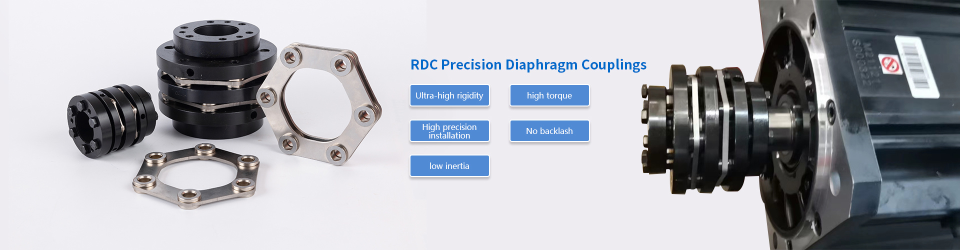
Gear coupling dimensions revolve around sleeve length, tooth form, hub OD and lubricant volume. They carry high torque in a small envelope, yet need grease and regular inspection. Misalignment allowance per gear mesh is small, so double-engagement sleeves are common. Disc coupling dimensions, including diaphragm designs, focus on disc pack diameter and spacer length. There is no lubrication and no backlash, which is why servo, spindle and high-speed pump duties favour them. Their axial tolerance is narrow, so the DBSE must be set accurately.
Pin bush coupling dimensions and tyre coupling dimensions
Pin bush coupling dimensions are defined by pin pitch circle diameter, pin and bush count, flange OD and gap. The design is common on cooling tower fans, conveyors and mill drives. Tyre coupling dimensions centre on flange diameter, tyre width and permitted axial float. A high-elastic tyre handles large misalignment and torsional shock, at the cost of a larger outer diameter. Confirm whether the tyre can be replaced without moving the motor, since that affects maintenance time.
Table 1: Flexible coupling dimensions to verify first, by coupling type
| Coupling type | Dimensions to verify first | Typical duty |
|---|---|---|
| Jaw / spider | Bore range, hub OD, spider thickness, overall length | Small pumps, compressors, light conveyors |
| Gear | Sleeve length, hub OD, tooth form, gap | High-torque drives, heavy conveyors |
| Disc / diaphragm | Spacer length, disc pack OD, DBSE, axial tolerance | Servo, machine tools, high-speed pumps |
| Pin bush | Pin pitch circle, flange OD, gap, bush width | Fans, mills, general industrial drives |
| Tyre | Flange OD, tyre width, axial float, bore range | Shock-loaded or misaligned drives |
Dimension sets are not interchangeable across makers. A spider that looks identical may differ by a millimetre in thickness or by a hardness step, so cross-reference flexible coupling dimensions and rated values, never a visual match alone. A manufacturer that offers diaphragm, jaw-spider and high-elastic couplings in one range, plus ETP hydraulic expansion bushes for keyless clamping, lets a buyer compare dimension sets without switching suppliers. Compare on the data sheet, not on the family name.
Standard sizes, bore tolerances and keyway data
Indian engineers usually work with three reference sets: motor frames to IEC 60072 and IS 1231, parallel keys to IS 2048 or DIN 6885, and coupling standards such as IS 2693 for pin-type flexible couplings and DIN 740 for torsionally flexible couplings. Cross-checking all three prevents most fitment surprises in flexible coupling dimensions.
What do flexible coupling standard sizes IS BIS DIN actually cover?
Flexible coupling standard sizes IS BIS DIN mostly standardise mounting interfaces, preferred bores, keyways and, for pin-type designs, the principal envelope. Torque ratings and elastomer grades often remain manufacturer-specific, so two couplings of one nominal size from different makers can differ in capacity. BIS (Bureau of Indian Standards) publishes the IS series, while DIN remains widely referenced in OEM drawings, especially for imported machinery. Confirm the current edition before quoting any standard in a purchase specification.
Flexible coupling bore size and keyway dimensions for common motor frames
The table below lists shaft diameters for standard 4-pole and slower IEC motors with the matching parallel key. Two-pole motors in larger frames use smaller shafts, so verify against the motor nameplate.
Table 2: Motor frame, shaft diameter and parallel key
| IEC frame | Shaft diameter (mm) | Key width × height (mm) |
|---|---|---|
| 71 | 14 | 5 × 5 |
| 80 | 19 | 6 × 6 |
| 90 | 24 | 8 × 7 |
| 100 / 112 | 28 | 8 × 7 |
| 132 | 38 | 10 × 8 |
| 160 | 42 | 12 × 8 |
| 180 | 48 | 14 × 9 |
| 200 | 55 | 16 × 10 |
| 225 (4-pole) | 60 | 18 × 11 |
| 250 (4-pole) | 65 | 18 × 11 |
Source: values based on IEC 60072-1 and DIN 6885-1; verify against the current edition and the actual motor.
Bore tolerance is typically H7 on the coupling, with shafts in k6 or m6 for a light transition fit, but follow the supplier's recommendation. Where a keyway is undesirable, keyless hydraulic expansion bushes such as the ETP type can clamp the shaft without a key. The data sheet should then state the clamping bore instead of a keyway.
A short word on units. Older imported machines still carry inch dimensions, so convert and write the unit next to every figure. A 1.5 inch shaft is 38.1 mm, not 38 mm, and that 0.1 mm decides whether an H7 bore slides on cleanly.
How do you use a flexible coupling dimension chart PDF?
Request a flexible coupling dimension chart PDF from the manufacturer and read it in a fixed order: size designation, bore range, rated and maximum torque, speed, then outer dimensions. Note the revision date, because dimensions can change between catalogue editions. Many plants keep a one-page internal flexible coupling size chart for the pumps and motors they own. In our experience, a simple spreadsheet listing motor frame, shaft, key and installed coupling size is worth more than a thick catalogue during a night-shift failure.
Flexible coupling selection guide with a worked example
Select by torque first, then bore and keyway, then misalignment and space, and finally speed and environment. Skipping that order is how oversized hubs and undersized elastomers end up on the same shaft.
Step-by-step flexible coupling selection guide
- Collect duty data: motor power (kW), speed (rpm), driven machine, running hours per day and starts per hour.
- Calculate nominal torque with T = 9550 × kW ÷ rpm.
- Apply the manufacturer's service factor to obtain design torque.
- Compare design torque with the flexible coupling torque rating, and peak torque with the maximum rating.
- Check both bore sizes and keyways against the coupling's bore range, using measured shaft diameters.
- Verify DBSE, hub lengths, outer diameter and guard clearance against the installation drawing.
- Confirm speed limit, balance requirement, temperature and chemical exposure, then finalise the element material.
This sequence works for every family, whether you pick a jaw, gear, disc, pin bush or tyre type. Service factors are manufacturer-specific, but as rough guidance, uniform loads such as centrifugal pumps often start near 1.0 to 1.25, moderate shock such as reciprocating compressors may need 1.5 or more, and heavy shock duties such as crushers can need 2.0 or higher. Defer to the catalogue.
Worked example: 7.5 kW motor driving a centrifugal pump
The following is an illustrative scenario with assumed values, not a client record.
- Motor: 7.5 kW, 4-pole, 1440 rpm, frame 132, shaft 38 mm with a 10 × 8 mm key
- Pump: shaft 32 mm with a 10 × 8 mm key, assumed 10 hours per day and a few starts per day
- Nominal torque: 9550 × 7.5 ÷ 1440 ≈ 49.7 Nm
- Assumed service factor 1.5, so design torque ≈ 74.6 Nm
- Requirement: a coupling rated at or above 75 Nm whose bore range covers both 32 mm and 38 mm
- Assumed DBSE: 50 mm, which the chosen size must accommodate
Next, read the size chart. Pick the smallest size whose rated torque exceeds 75 Nm and whose maximum bore is at least 38 mm. If a size meets the torque but its maximum bore is only 35 mm, move up one size, even though capacity then sits well above need. Finally, check hub OD against the guard and confirm the speed rating exceeds 1440 rpm, which is almost always true in this size range. A jaw-spider or pin bush type would normally be shortlisted. If the pump is sensitive to alignment drift, a spacer disc type is the alternative.
Can one coupling size fit different shaft diameters?
Yes, within the bore range printed for that size. A single hub body is often bored for several shaft diameters, and each pairing needs its own keyway. The limit is wall thickness and torque derating at the top of the range, so read the manufacturer's data rather than assuming the maximum bore carries full rated torque.
Common dimensional mistakes and supplier checks
The most frequent flexible coupling dimensions mistakes are guessing the bore, ignoring the keyway, mis-measuring DBSE and choosing by motor power alone. Each is avoidable with a five-minute check before purchase.
Which dimension errors shorten coupling life?
- Bore taken from the motor frame without measuring the driven shaft, which may be worn or non-standard.
- Keyway width mismatch between metric and legacy inch keys.
- DBSE set too tight, loading discs or elastomers axially, or too wide, leaving jaws poorly engaged.
- Hub OD touching the guard or bracket after thermal growth.
- Torque rating compared with motor power instead of design torque.
Why do these slip through so often? Dimension checking feels trivial, and the failure appears months later as a bearing replacement, far from the cause. A pre-installation checklist signed by the fitter removes most of that risk.
Consider an illustrative composite case. A maintenance team replaced a spider coupling on a 15 kW blower every few months. A review found the hub had been bored to 40 mm and shimmed to suit a 38 mm shaft, leaving a loose fit. Re-measuring the shaft, specifying the correct bore and fitting a proper key ended the repeat failures. This reflects common field patterns and is not a named customer.
What should you check among flexible coupling manufacturers in India?
When comparing flexible coupling manufacturers in India, or overseas suppliers serving Indian plants, judge dimensional discipline rather than brochures alone. Ask for a dimensioned drawing for each size, bore and keyway tolerance statements, the balance grade where relevant, and the basis of each torque rating. In-house CNC machining, dynamic balancing machines and a dynamic torque tester make such claims verifiable. One manufacturer setup, for example, includes a tester up to 10,000 Nm. Service response matters too, because a breakdown rarely waits for a quotation cycle. A listed capability is not a certification, so ask for the actual document.
Pricing and lead time vary by size, material and order quantity. Request written quotations on the same specification before comparing offers.
Conclusion: flexible coupling dimensions decide performance
Key takeaways
- Bore, keyway, length and DBSE govern fit, torque capacity and misalignment tolerance.
- Use IS, BIS and DIN data as a cross-check, then confirm with the manufacturer's data sheet.
- Calculate design torque before opening the size chart.
Next step for your drive
Flexible coupling dimensions are not a detail to settle after the purchase order. Measure the shafts, compute design torque, read the dimension chart carefully and keep a one-page record of what is installed. That small discipline turns flexible coupling dimensions into a reliability tool instead of a recurring breakdown cause. For specific drives, consult the manufacturer's application engineers.
Frequently asked questions
Q: What are the main flexible coupling dimensions to check before buying?
A: Check bore diameter, keyway width and depth, hub outer diameter, overall length, DBSE and the rated torque. Compare each against your measured shaft sizes and installation space, using the manufacturer's flexible coupling size chart.
Q: How do flexible coupling dimensions affect machine performance?
A: They set torque capacity, misalignment tolerance, rotating inertia and shaft fit. Incorrect dimensions raise bearing loads, vibration and heat, which shortens the life of the coupling and connected machines.
Q: Which standards apply to flexible coupling sizes in India?
A: Commonly referenced are IEC 60072 and IS 1231 for motors, IS 2048 or DIN 6885 for keys, IS 2693 for pin-type couplings and DIN 740 for torsionally flexible couplings. Confirm current editions with the supplier.
Q: How do I calculate the torque needed for coupling selection?
A: Use T (Nm) = 9550 × power (kW) ÷ speed (rpm), then multiply by the service factor. Select a coupling whose rated torque exceeds that design torque and whose maximum torque covers peak loads.
Consult immediately
If you are interested in our products, please leave your email address, and we will get in touch with you as soon as possible. Thank you!
Kunshan Haozong Transmission Technology Co., Ltd.
Contact: Manager Liu 13372152786 (WeChat)
Email: liu@hz-coupling.com
Address: Room A5-304, No. 18 Jinxing Road, Huaqiao Town, Kunshan City, Jiangsu Province

Scan the mobile website