
Discuss the mechanical principle of diaphragm coupling in detail
2022-06-25 08:42
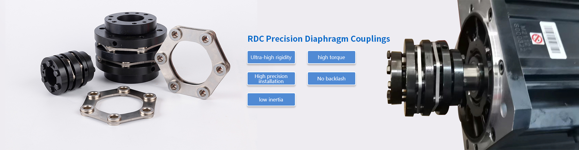
The diaphragm coupling is connected by the diaphragm and the two halves of the coupling with bolts staggered or other ways. Each group of diaphragms is formed by stacking several pieces. Shaped whole piece. In addition, the diaphragm coupling mainly relies on the elastic deformation of the diaphragm to compensate the displacement of the two shafts. This is a high-performance flexible coupling. The diaphragm coupling does not require lubrication, has a compact structure, and has a long service life. High strength and no rotation gap, it will not be affected by temperature and oil pollution, and has the characteristics of acid resistance, alkali resistance and anti-corrosion, so it is very suitable for shafting transmission in high temperature, high speed, and corrosive medium working conditions. So how much do you know about the mechanical principle of the diaphragm coupling? Now let me analyze it for you.
1. Before installing the diaphragm coupling, the prime mover should be checked first
Check whether the two shafts of the working machine are concentric, whether there is wrapping paper or bumps on the surfaces of the two shafts, whether there are debris in the inner holes of the two half couplings of the diaphragm coupling, and whether the edges of the inner holes are bumped. If there are these problems, the shaft and half coupling should be cleaned up, and the bruise should be treated with a fine file. Then check whether the diameter and length of the inner hole of the two half couplings are consistent with the diameter and length of the shaft extension of the prime mover and the working machine. In general selection, it is better to let the length of the half coupling at the end of the prime mover and the working machine be less than the length of its shaft extension by 10-30mm.
2. In order to facilitate the installation of the diaphragm coupling
It is best to preheat the two half couplings in a 120--150 incubator or oil tank, so that the size of the inner hole is enlarged and it is easy to install. After installation, ensure that the shaft head cannot protrude from the end face of the half coupling, preferably flush. Detect the distance between the two half couplings of the diaphragm coupling: measure the readings of 3--4 points along the inner sides of the flanges of the half coupling and take the average value, and measure the lengthened section and the two diaphragm groups. The sum of the size, the error of the two is controlled within the range of 0-0.4mm.
3. Diaphragm coupling alignment
Use a dial indicator to detect the runout of the flange end face and outer circle of the two halves of the coupling. When the outer circle of the flange is less than 250mm, the runout value should not be greater than 0.05mm; when the flange outer circle is greater than 250mm, the runout value should not be greater than 250mm. greater than 0.08.
4. Install the diaphragm coupling bolts
Insert the bolt from the outside of the small hole of the flange, and pass it out from the outside of the large hole of the other piece of flange, put on the buffer sleeve, elastic washer, twist the nut, and tighten the nut with a wrench. If it is uncomfortable to install or dismantle and replace, without damaging the shaft and half-coupling, it is better to rotate freely after installation.
5. Instructions for Diaphragm Coupling Operators
Before starting the equipment, the shaft should check whether the nut of the diaphragm coupling is loose or fall off. If necessary, tighten the nut with a wrench in time.
Kunshan Haozong Transmission Technology Co., Ltd.
Contact: Manager Liu 13372152786 (WeChat)
Email: liu@hz-coupling.com
Address: Room A5-304, No. 18 Jinxing Road, Huaqiao Town, Kunshan City, Jiangsu Province

Scan the mobile website